Solidworks Lego Man Part 3, Part and Assembly Drawings

Now that we had all our parts and assemblies it is time to create some technical drawings so that they can be reproduced.


While double checking my works I found out that some of my parts were labeled wrong so I hanged their names not knowing that it would cause me some major problems. All the files that were linked to those parts had to be redone, this included my full assembly drawing, my sub assembly drawing and the assemblies themselves. 

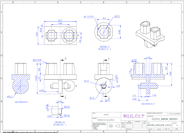
This is the part drawing for the Lego mans waist, it looks like a super simple part but it actually has quite a lot going on and it was challenging getting all the information on there making sure that no information was left out. 

This Sub assembly drawing contains a lot less information and just includes basic dimensions for when everything is put together, it also clearly labels the parts that would usually have their own part drawing containing all their individual features & dimensions.

This drawing shows all the sub assemblies together and much like the drawing above only includes basic dimensions for the overall assembly. It also includes some detail views that help better communicate parts that might be hard to see on the smaller sections of the drawing.

The drawings is something that I can definitely work on, making sure you include all the features and dimensions required to manufacture the part is important and it has to be set up neatly so that you can actually read and understand it. Later on when I discovered that by using the pack and go feature in Solidworks you can easily rename parts while keeping the links, this would have saved me loads of time earlier but now I know for next time.

Comments